TIP3055 Introduction
The TIP3055 is a popular NPN power transistor. It is commonly used in power amplifiers, switching regulators, and motor control circuits due to its ability to handle high voltages and currents, with a maximum collector current of 15A and a collector-emitter voltage of 60V. The versatility and widespread availability of TIP3055 transistor have made it a staple in power electronics design.
TIP3055 Pinout

The TIP3055 is a power transistor with three pins, each serving a distinct function in its operation. Here's a description of the pinout:
Base (B): This is the control pin of the transistor. A small current applied to the base controls the larger current flow between the collector and emitter.
Collector (C): The collector is the pin through which the main current enters the transistor. When the transistor is turned on, current flows from the collector to the emitter.
Emitter (E): The emitter is the pin through which the current leaves the transistor. In an NPN transistor like the TIP3055, current flows from the collector to the emitter.
TIP3055 Models

TIP3055 Circuit

TIP3055 Specification
| Specification | Value |
| Type | NPN Power Transistor |
| Collector-Emitter Voltage (Vceo) | 15 V |
| Voltage - Collector Emitter Breakdown (Max) | 60 V |
| Vce Saturation (Max) @ Ib, Ic | 3V @ 3.3A, 10A |
| Current - Collector Cutoff (Max) | 700µA |
| DC Current Gain (hFE) (Min) @ Ic, Vce | 20 @ 4A, 4V |
| Power - Max | 90 W |
| Emitter-Base Voltage (Vebo) | 5 V |
| Collector Current (Ic) | 15 A |
| Base Current (Ib) | 4 A |
| Gain Bandwidth Product (fT) | 2 MHz |
| DC Current Gain (hFE) | 20 to 70 |
| Transition Frequency (fT) | 2 MHz |
| Package Type | TO-247-3 |
| Thermal Resistance Junction to Ambient | 1.1°C/W |
| Operating Temperature | 150°C (TJ) |
TIP3055 Features
High Collector Current
High Power Dissipation
Robust Voltage Ratings
High Gain Bandwidth Product
Wide Temperature Range
Stable DC Current Gain
Good Thermal Resistance
Low collector-emitter saturation voltage
Complementary NPN - PNP transistors
TIP3055 Applications
General Purpose
Audio Amplifier
DC Motor Drivers
Power Supply Circuits
Switching Regulators
High-Current Load Switching
Relay Drivers
Linear Voltage Regulators
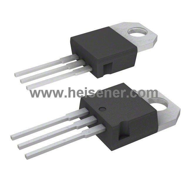
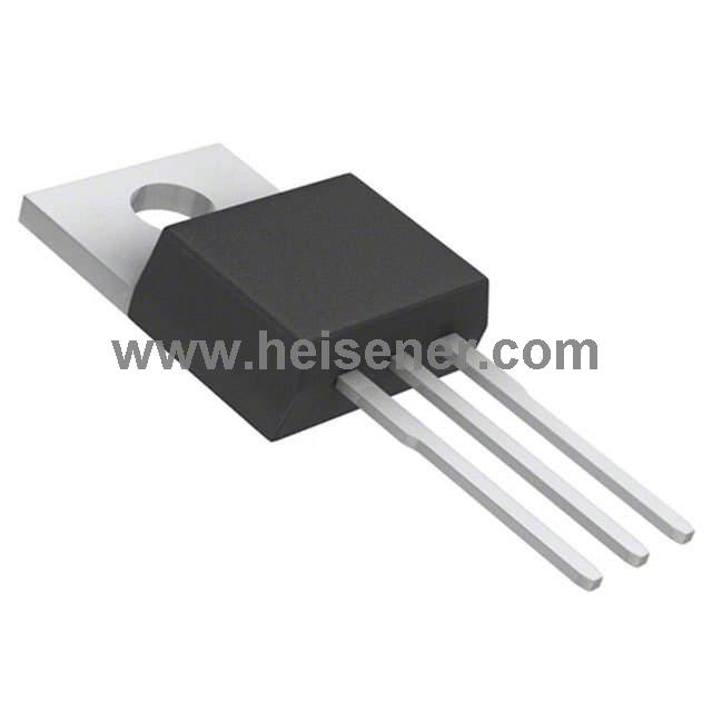
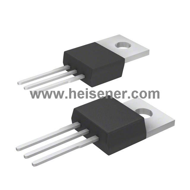
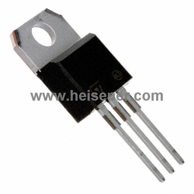
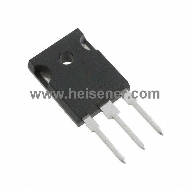
TIP3055 Package
The TIP3055 is packaged in a TO-247-3 enclosure, which is a through-hole package type designed for high-power semiconductor devices. The TO-247-3 package features three pins and a large metal heatsink, making it suitable for high-current and high-power applications. The package includes three pins: Collector (C), Base (B), and Emitter (E). The large metal heatsink is typically connected to the Collector, providing an efficient path for heat dissipation.

How to Use TIP3055?
To use the TIP3055, start by preparing the necessary circuit and connection materials, including the power supply, load, and resistors. Next, connect the TIP3055's three pins to their corresponding positions in the circuit: the collector (C) pin typically connects to one end of the load, the emitter (E) pin connects to the negative terminal of the power supply, and the base (B) pin is used for the control signal input.
Then, ensure that the TIP3055's metal heatsink is securely attached to a heat sink or cooling surface. Afterward, connect the power supply and load, and apply the control signal to the base pin. Finally, check the circuit's operation to ensure everything is functioning correctly.
FAQs
What is TIP3055?
The TIP3055 is an NPN power transistor for high-current and high-power applications. It is used in a variety of electronic circuits to amplify or switch electrical signals.
What are the alternative transistors to the TIP3055?
Alternatives to the TIP3055 include TIP3055G, TIP35A, TIP35AG, TIP35B, TIP35BG, TIP35C, TIP35CA, and TIP35CG. These transistors are similar in function but may differ in packaging, gain characteristics, or maximum ratings.
What precautions should be taken when using the TIP3055?
When using the TIP3055, ensure:
Adequate heat dissipation through proper heat sinking.
Avoid exceeding the maximum rated voltage and current to prevent damage.
Proper connection of the collector, base, and emitter terminals to avoid short circuits and ensure correct operation.