The MIC5239 is a low-static current, µCap low-drop regulator. Using thermal enhanced SOIC-8, SOP-8 and SOT-223, fixed 1.5V, 1.8V, 2.5V, 3.0V, 3.3V and 5.0V with adjustable voltage. With a maximum working input voltage of 30V and a static current of 23μa, it is ideal for providing maintenance power in high-voltage battery systems.
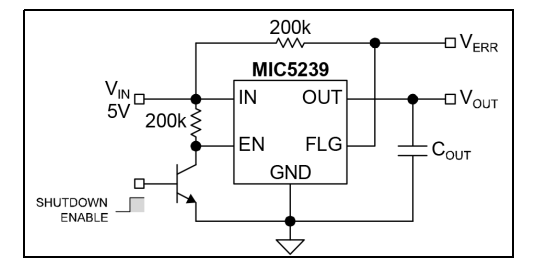
Typical Application Circuit

The MIC5239 has an output capacity of 500 mA and a voltage drop of only 350 mV. It can provide high output current for applications such as USB. As a μ Cap LDO, the MIC5239 is a stable ceramic or tantalum output capacitor. It requires only 3.3μF output capacitance for stability.
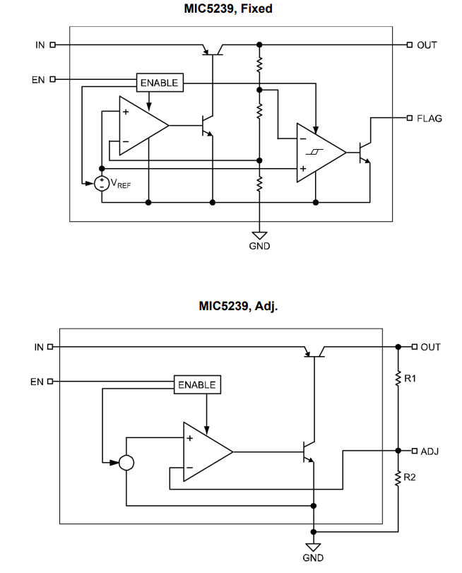
Functional Block Diagram

The MIC5239 includes a logically-compatible enable input and undervoltage error flag indicator. Other features of the MIC5239 include thermal shutdown, current limiting, overvoltage shutdown, reverse leakage protection and reverse battery protection.
Package Types

Features
• Ultra-Low Quiescent Current (IQ = 23µA@IO = 100µA)
• Continuous 500 mA Output Current
• Wide Input Range: 2.3V to 30V
• Low Dropout Voltage: 350 mV @500 mA
• ±1.0% Initial Output Accuracy
• Stable with Ceramic or Tantalum Output Capacitor
• Logic Compatible Enable Input
• Low Output Voltage Error Flag Indicator
• Overcurrent Protection
• Thermal Shutdown
• Reverse-Leakage Protection
• Reverse-Battery Protection
• High-Power SOIC-8, SOP-8, and SOT-223 Packages
Applications
• USB Power Supply
• Keep-Alive Supply in Notebook and Portable Personal Computers
• Logic Supply from High Voltage Batteries
• Automotive Electronics
• Battery-Powered Systems
Enable a low level on the pin to disable the part, forcing the static current to be less than 0.1μA. Hot shutdown and error flags do not work when the device is disabled. For 2.0V inputs, the maximum energy bias current is 2µA. The open collector pull-up resistance relative to the input voltage should be set low enough to maintain 2V on the enable input. The figure below shows an open collector output drive enabling the pin to bind to the input voltage via a 200 kΩ pull-up resistor. To avoid output oscillations, slow transitions from low to high levels should be avoided.
